ISO 21857 - Evaluating DC Stray Current Voltages

ISO 21857 - Evaluating DC Stray Current Voltages

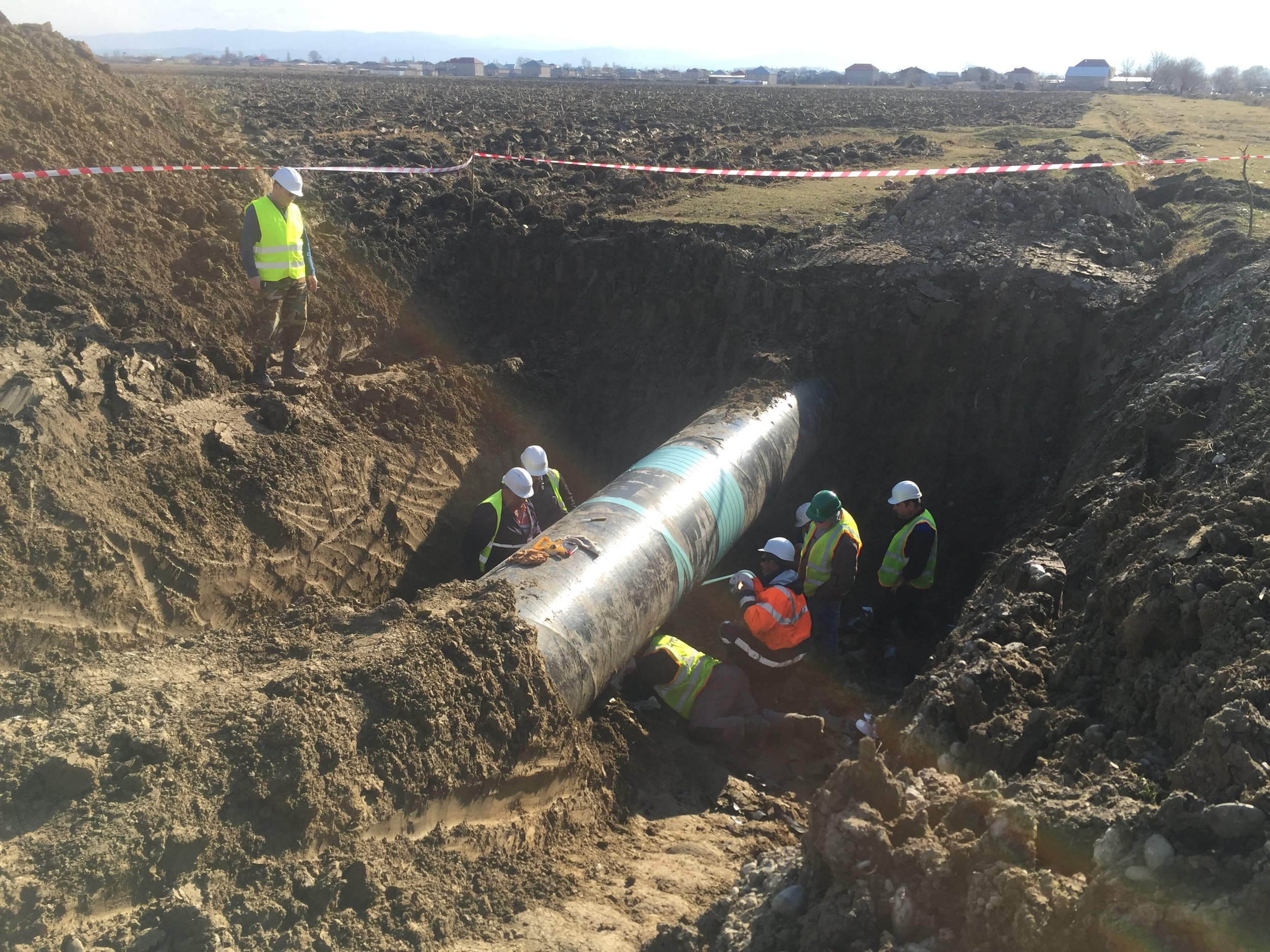
Interference from dc traction systems can result in pipe-to-soil potentials outside of the acceptable limits.

The Q method is an established procedure for evaluating the time varying potentials and empirical guidelines have been developed to allow a judgement of the corrosion risk caused by the interference.

The method can be used to evaluate current densities as well as potentials.

Next Generation Transformer-Rectifiers for Cathodic Protection Applications

Corroconsult UK Limited are proud to announce a new product line.

This next generation of transformer-rectifiers offer the user absolute control over the TRs configuration in real-time with the added benefit of in-built remote monitoring of key measurements.

The TRs can be viewed and configured in real-time through web based applications that are compatible with Windows / Macintosh / Android / iOS platforms.

Each initial order is provided with a lifetime single user access to the online database (additional lifetime user licenses can be purchased separately). There are no hidden ongoing subscription costs.

Each unit can be designed specifically to client requirements and is assembled and tested in the UK by Corroconsult personnel in accordance with the Company Quality Management System (ISO 9001-2015).

Take control of your impressed current cathodic protection (ICCP) systems.

Contact us for a live demonstration via video conferencing.

UVDB Verify B1 Audit - 100% Pass Mark Achieved

Corroconsult are pleased to announce the result of their latest UVDB Verify Audit (Category B1) has seen the Company achieve a 100% pass mark in all aspects.

This is in no small part to the ongoing contributions to the QHSE management systems being monitored and implemented by both Peter Rosie (Office Manager) and Diane Singleton (Business Support Manager).

A special mention also goes to Anthony Thomas (Corrosion Engineer) for hosting the UVDB auditor during his on-site inspection.

This flawless mark is indicative of our Company’s dedication to not only seeking to monitor our QHSE systems, but to also pro-actively improve them.

Supplier Name: Corroconsult UK Limited

Supplier ID: 61703

Audit Level: Verify B1

Audit Date: 22/08/2019

MSE

CSR: 100%

Environmental: 100%

Health and Safety: 100%

Quality: 100%

SITE

Environmental: 100%

Health and Safety: 100%

Quality: 100%

Introduction to Kirchoff's Law & Network Analysis

The following paper was presented at CEOCOR – Brussels, Belgium – 19th – 22nd May 2014.

The paper was authored by Ken Lax, and presented by Ken at the conference.

DISCLAIMER: All information, references to Standards and / or criteria correct at time of paper.

Introduction

Kirchhoff’s Laws are the foundation for many network analysis techniques. 

Cathodic Protection systems are essentially d.c. electrical networks and the distribution of current follows these laws.

Most CP applications will not require any knowledge of these laws but sooner or later every CP practitioner will need to apply and understand them.

By the end of this presentation you will be able to apply Kirchhoff’s Laws and resolve the simultaneous equations using matrix algebra.

An understanding of Kirchhoff’s Laws, and the ability to apply them, will enable you to understand:

  • I-V equivalent circuits (source transformations)
  • Superposition applications
  • Mesh networks
  • LaPlace transformations (not covered in this presentation)
  • Node Voltage Analysis (NVA)
  • Thevenin and Norton Theorems (not covered in this presentation)

We will only be considering d.c. circuits in this introduction.

AGENDA

  • Circuit definitions (branch, junction, node)
  • Definition of Kirchhoff’s Current Law (KCL)
  • Definition of Kirchhoff’s Voltage Law (KVL)
  • Some warm-up exercises with Ohms Law
  • Simple rules for applying KCL and KVL to produce independent simultaneous equations
  • KCL and KVL exercises with increasing complexity
  • Simple way to solve simultaneous equations using Excel
  • Solving simultaneous equations using augmented or inverted matrix operations

OVERVIEW

OVERVIEW.png

Kirchoff's Current Law (KCL) and Kirchoff's Voltage Law (KVL) will add to the existing knowledge of CP engineers and designers and help to explain some of those mysterious situations that cannot be explained just by Ohms Law.

DEFINITIONS

Passive sign convention:  Current enters a passive device at its POSITIVE terminal.

Current:  Measurement of the electric charge passing through a given point within a certain amount of time.  Units are Coulombs per second (amperes).

Voltage:  measures the amount of energy required to move a given amount of charge as it passes through a circuit.  Units are Joules per Coulomb (Volts).

Junction:  Any place where two or more wires come together.

Branch:  Anything that connects two junctions

Node:  A point in the circuit

KIRCHOFF'S CURRENT LAW (KCL)

Also known as the JUNCTION rule.  Conservation laws tell us that electrons must behave in a certain way when connecting devices to make a circuit.   The electron behaviour governs the voltage and current around the loops and at the nodes.  So Kirchhoff’s Laws apply whatever devices are used in the circuit since it is a law of conservation of charge (KCL) or energy (KVL).

The sum of the currents entering any junction must equal the sum of the currents leaving that junction.

KIRCHOFF'S VOLTAGE LAW (KVL)

OVERVIEW.png

Also known as the LOOP rule. 

The sum of the potential differences across all elements around any loop must be zero.

The Importance of Electrical Isolation

Defining "Electrical Isolation" for a Cathodic Protection System

With respect to cathodic protection systems, the term "electrical isolation" relates to confining the (cathodic) protective current to the structure being protected.

In terms of electrical separation this could mean isolating;

  • Two (or more) cathodic protection systems from one another
  • Buried / immersed structures from above ground appurtenances
  • Cathodically protected structures from earthing systems
  • Owner / Operator interfaces

Electrical isolation is a key factor in the successful application of cathodic protection where it has been included at the design stage. For the purposes of this blog article we assume that the structure is intended to be electrically isolated.

That is not to say that electrical isolation is always required, as long as the designed system has taken this into account.

There are times when it may not be desirable, or even practical, to isolate protected from unprotected structures. Examples are refineries, industrial plants, large tank farms and similar complex facilities. 

How to Electrically Isolate the Cathodically Protected Structure

Commercial fittings for providing electrical isolation of pipework include;

  • Insulating Flange Kits (IFK)
  • Monolithic Isolation Joints (IJ)
  • Non-metallic pipe sections

Cathodically protected structures can be electrically isolated from earthing systems via;

  • Decoupling Devices

Other solutions, e.g. non-conductive membranes, are available as methods of electrical isolation depending on the system in question.

Insulating Flange Kits (IFK)

Insulating Flange Kit (Exploded View) resized.jpg

The kit comprises of the following;

  • Insulating Gasket
  • Non-Metallic Sleeves for Assembly Bolts
  • Non-Metallic Washers
  • Metallic Washers
  • Nuts & Bolts

Monolithic Isolation Joints (IJ)

Monolithic Isolation Joint resized.jpg

The isolation joint is fabricated as a ready to install section of pipework.

The joint consists of;

  • Forged Rings
  • External Coating
  • Internal Coating
  • Adhesive Sealant
  • Di-Electric Filler
  • Insulating Rings
  • O Rings

Decoupling Devices

Corroconsult recommend only solid-state devices, as this eliminates the maintenance requirements and hazardous electrolytes of electrochemical polarisation cells.

acdd.jpg

Solid-state DC decoupling devices can be used for;

  • Electrically isolating from from utility earthing (grounding) systems
  • Electrically isolating from electrical equipment earthing (grounding) systems
  • Induced AC voltage mitigation
  • Isolation joint protection

How can electrical isolation be compromised?

Incorrect Installation

An incomplete kit installation for an IFK will result in the flanged joint being electrically continuous.

Earthing / Grounding

The most common failure of installed electrical isolation is through incorrect earthing of cathodically protected structures.

DCVG Survey - A Beginner's Guide [Part 1]

Direct Current Voltage Gradient [DCVG] Survey

Introduction

This non-intrusive, above ground survey allows the operator to identify the location of coating defects (holidays).

We are pleased to announce the first uploaded animation to our YouTube channel (shown within this post).

The YouTube video represents the first instalment within a series. Its purpose is to give an introductory overview to people not familiar with the technique e.g. asset owners, operators, supervisors.

Recognition within International Standards for Buried Pipelines

The technique is an approved ECDA (External Corrosion Direct Assessment) method as detailed in ANSI / NACE Standard Practice SP 0502-2010.

DCVG is also listed as an above-ground survey used to assess the coating condition and to locate coating defects within:

  • BS EN 13509:2003 - Cathodic protection measurement techniques
  • BS EN ISO 15589-1:2017. Petroleum, petrochemical and natural gas industries. Cathodic protection of pipeline systems. On-land pipelines

All DCVG surveys should be undertaken by competent and qualified personnel in accordance with BS EN ISO 15257:2017 - Cathodic protection - Competence levels of cathodic protection persons.


This short animation shows the technique to be utilised for a DCVG (Direct Current Voltage Gradient) survey using an analogue voltmeter and matched electrodes.

The video covers the basic methodology in identifying, centering and measuring coating defects (holidays) in the field [OL/RE Potential]

This "How To" guide is intended for asset owners, operators and supervisors that may not be familiar with the technique.


An Overview of the ECDA Process

What does ECDA mean?

ECDA is the commonly used acronym for External Corrosion Direct Assessment. The process has been developed for buried onshore ferrous pipeline systems. ECDA was created as a process for improving pipeline safety. Its primary purpose being to prevent future external corrosion.

Whilst this post attempts to provide an overview of the ECDA process, it is imperative that it is tailored each time to address specific requirements of individual pipeline systems.

What are the main steps of the ECDA Process?

There are four main steps to the ECDA Process, these are;

  • Pre-Assessment [Desktop Study]
  • Indirect Assessment [Above Ground / Non-Intrusive Surveys]
  • Direct Assessment [Bellhole Excavation & Testing]
  • Post Assessment [Calculation & Reporting]

The flow diagram below shows a general approach to the ECDA Process - evaluation methods may include, but are not limited to those shown here.


Pre-Assessment

Pipe Related

  • Material
  • Diameter
  • Wall Thickness
  • Year Manufactured
  • Seam Type
  • Bare Pipe Sections

Construction Related

  • Year Installed
  • Route Changes / Modifications
  • Construction Practices
  • Locations of Valves, Clamps, Insultaing Joints etc
  • Locations of and Construction Methods used at Casings
  • Locations of Bends including Miter Bends and Wrinkle Bends
  • Depth of Cover
  • Underwater Sections / River Crossings
  • Locations of River Weights and Anchors
  • Proximity to other Pipelines, Structures, HV Transmission Lines, Rail Crossings

Soils / Environmental

  • Soil Characteristics / Types
  • Drainage
  • Topography
  • Land Use (Current and Past)
  • Frozen Ground

Corrosion Control

  • CP System Type (Anodes, Rectifiers and Locations)
  • Stray Current Sources / Locations
  • Test Point Locations (or Pipe Access Points)
  • CP Evaluation Criteria
  • CP Maintenance History
  • Years without CP Applied
  • Coating Type – Pipe
  • Coating Type – Joints
  • Coating Condition
  • Current Demand
  • CP Survey Data / History

Operational Data

  • Pipe Operating Temperature
  • Operating Stress Levels and Fluctuations
  • Monitoring Programs (Coupons, patrol, Leak Surveys etc)
  • Repair History / Records
  • Leak / Rupture History
  • Evidence of Microbiologically Influenced Corrosion (MIC)
  • Type / Frequency of Third Party Damage
  • Hydrotest Dates / Pressures

Indirect Assessment

TR & Groundbed Functionality Checks

  • TR Output Current
  • TR Output Voltage
  • Drain Point Potential measurement
  • Groundbed Output Capabilities

CIPS (Close Interval Potential Survey)

  • Synchronously Interrupted
  • On Potential Measurement
  • Instant Off Potential Measurement

DCVG (Direct Current Voltage Gradient) Survey

  • Synchronously Interrupted
  • OL / RE Measurement
  • % IR at Defect Calculation

Additional Information Collated

  • GPS Coordinates recorded for key features and locations
  • Distance measurement of key features and locations
  • Photographic records taken for key features
  • a.c. potentials measured at all test facilities
  • Overview of condition of test facilities and associated connections
  • Data logging at identified / possible sources of Stray Current

Direct Assessment

Locations for excavation shall be selected based on the information gleaned from the pre-assessment and indirect assessment procedures.

A minimum of at least one trial pit should  be excavated to clarify the effectiveness of the first two procedures.


Post Assessment

All data obtained during the survey activities is provided, generally in both graphical and tabular formats (where appropriate), as well as photographic records, etc.

Updated Website Released

New Website Home.png

Corroconsult UK Limited are pleased to announce the release of our updated website.

The new site includes expanded sections regarding our services and material data sheets as well as new client and project gallery sections.

We hope that you enjoy the new content, and will be looking to add further information over the coming months.

ISO & OHSAS Accreditation Renewed


Corroconsult are proud to announce the renewal of their ISO and OHSAS certification following today's audit.

Following on from last years successful audit to the latest ISO standards for Quality and Environmental management systems, Corroconsult remain one of the few corrosion companies to have already been recognised with this accreditation.

Full versions of our current certificates can be found using the links below;