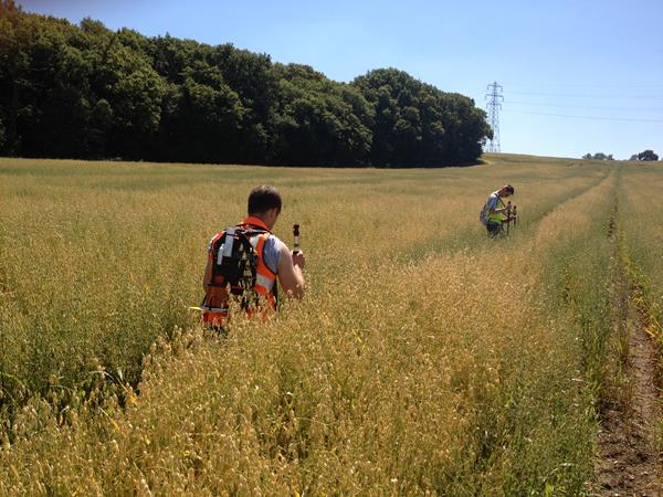
external corrosion direct assessment (ECDA) Surveys

ECDA (External Corrosion Direct Assessment) is a method for evaluating the seriousness and extent of external corrosion.  Using this information it is possible to calculate the remaining strength of the pipeline and hence the maximum allowing operating pressure (MAOP).  It is also possible to estimate the corrosion rate and thus determine the time to failure for a given pressure.

External corrosion is controlled by the application of resistive coatings, known as passive protection, and cathodic protection, known as active protection.  With few exceptions it is not possible to achieve a 100% effective passive protection.  For this reason the cathodic protection is applied to prevent corrosion at those areas where the coating has failed.

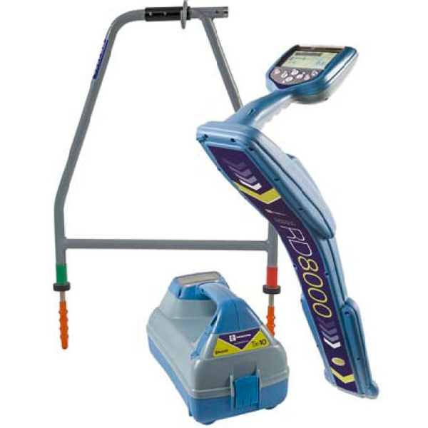
The ECDA, therefore, has to consider two principle corrosion protection failure mechanisms - the coating and the cathodic protection.  Once the failure locations have been identified it is necessary to undertake (direct) measurements of the pit depths and wall thickness around the full circumference of the pipe to calculate the MAOP and remaining life.

There are a number of methods to achieve this indirectly (through above ground surveys), and these are summarised here.

 
DCVG of Gas Pipeline in a Rural Environment

DCVG of Gas Pipeline in a Rural Environment

DCVG of Buried Pipework in Pressure Reducing Station

DCVG of Buried Pipework in Pressure Reducing Station

DIRECT CURRENT VOLTAGE GRADIENT (DCVG)

DCVG is an above ground, non-intrusive survey, which is primarily used for the accurate location of coating defects on buried pipelines. Where coating defects are identified the operator takes further measurements in order to provide a bench-mark severity rating for each location.

This survey technique can be used to obtain the following information;

  • Accurate location of coating faults
  • Approximate severity of coating faults
  • Recognise and locate interference from third party structures / CP systems
  • Identify optimum location for installation of DC stray current mitigation systems

DCVG can be carried out on Impressed Current Systems, Sacrificial (Galvanic) Anode Systems and Unprotected Pipelines.

The technique is suitable for;

  • Cross country pipelines (agricultural land, desert, jungle etc.)
  • Urban pipelines (where the structure is beneath concrete or asphalt)
  • Complex pipeline systems (such as Process Plants, Tank Farms and City Streets)

Corroconsult are an approved surveyor for DCVG Limited, a Company established by the co-inventor of the DCVG technique, Dr. John Leeds.

CLOSE INTERVAL POTENTIAL SURVEY (CIPS)

CIPS, sometimes referred to as CIS (Close Interval Survey), is an above ground, non-intrusive survey, which is used to accurately determine the effectiveness of a cathodic protection system along the entire buried or immersed pipeline route.

The effectiveness of cathodic protection on buried pipelines is generally assessed by reference to the pipe-to-soil potential measurements since all national Standards refer to a potential criterion of one sort or another.

The CIPS technique can be employed for both buried (onshore) and immersed (offshore) pipelines.

CIPS - Onshore Pipelines

Pipe-to-soil potentials measured at test points (typically installed at 1 to 2 kilometre intervals along the pipeline route) do not accurately reflect the pipe-to-soil potentials in between test points.

To overcome this, a close interval potential survey (CIPS) is undertaken, with pipe-to-soil potentials are measured at nominal 2 metre intervals.

Pipe-to-soil potentials measured when the cathodic protection current is flowing are influenced by the actual cathodic protection current. This causes a measurement error that has become known as an IR error (from Ohm’s Law: V = I x R volts).

To overcome this error the sources of impressed current cathodic protection (where applicable) to the pipeline are synchronously interrupted and the pipe-to-soil measurement taken after the currents have stopped flowing but before the pipe depolarises.

CIPS - Marine / Offshore Pipelines

Offshore pipelines are typically sacrificial anode systems, for which interruption cannot be performed to measure the IR Free (“Off”) Potentials. The international Standards give potential criterion based on “On” (i.e. uninterrupted) Potenials.

The premise of the measurement is much the same as Onshore, with a cable reel mounted to the rear of a survey vessel, providing a permanent connection to the pipeline onshore, and the data logging equipment on board. Reference electrodes are attached to the Sonar Tow Fish, and connected to the data logger on board.

CIPS (Close Interval Potential Survey) Onshore

CIPS (Close Interval Potential Survey) Onshore

 
Combined CIPS & DCVG Survey

Combined CIPS & DCVG Survey

 
CIPS (Close Interval Potential Survey) Offshore

CIPS (Close Interval Potential Survey) Offshore

ACVG Equipment - As used by Corroconsult

ACVG Equipment - As used by Corroconsult

ALTERNATING CURRENT VOLTAGE GRADIENT (ACVG) survey

An alternating current signal is applied to the pipeline using the Transmitter. Combining the Locator with an A-Frame delivers the following information from a single pass survey;

  • Sub-meter accuracy of pipeline route
  • Depth of pipeline at each measurement location
  • Coating Defect / Coating Holiday location accurate to 4" / 10cm

As with both the DCVG and CIPS, all survey data is can be easily integrated with Client GIS systems.

SITE Surveys

Corroconsult offer other site surveys that compliment key activities. These services are also offered individually (separate to cathodic / corrosion protection requirements) where required by a Client.

SOIL RESISTIVITY / EARTH RESISTANCE MEASUREMENTS

Soil resistivity measurements are made to provide an indication of the soil corrosivity and for use in anode groundbed, attenuation and earthing calculations. 

Soil corrosivity can be classified  as:

  • 0 – 10 ohm.m          severely corrosive
  • 10 – 50 ohm.m        corrosive
  • 50 – 100 ohm.m      moderately corrosive
  • > 100 ohm.m           slightly corrosive

The preferred unit of measurement is the ohm metre (not ohms per metre) (ohm.m) although values are often quoted in ohm centimetres (ohm.cm).  To convert ohm.m to ohm.cm multiply by 100.

Barnes Layer Analysis

Corroconsult can provide soil resistivity for both shallow and deep layer assessment as required, and full Barnes Layer Analysis provided for each assessed layer.

Installed System Resistance to Earth

The 3-point method, called the “fall of potential” method, can be used to evaluate the resistance of an installed earthing system or anode groundbed. This information can be utilised to verify that the installed system is compliant with the design requirements.

Soil Resistivity Measurements - Landfall Pipeline

Soil Resistivity Measurements - Landfall Pipeline

 
Soil Resistivity - Wenner 4 Pin Method

Soil Resistivity - Wenner 4 Pin Method

Buried services location within Pump Station

Buried services location within Pump Station

BURIED SERVICEs LOCATION


All Corroconsult field personnel are qualified NPORS (National Plant Operators Registration Scheme) Operators for Cable Avoidance Tools (Category N304).

Sub-meter accuracy of survey data is available as standard, with sub 10cm and sub 1cm accuracy available on request.

LRUT - Long RANGE Ultrasonic testing


Long Range Ultrasonic Testing (LRUT) provides a non-destructive means of inspection to detect corrosion, erosion and other defects in pipe work, for long lengths of pipe line from a single location. From this one location inspection can be achieved in both directions thus covering twice the range.

This technology can be used for pipes with diameters from 1.5” (38.1mm) to 48” (1219mm). There are further applications for which this technique has been developed. These include:

LRUT.jpg
  • Chemical plant: heat exchangers, embedded and cased pipes
  • Oil and gas: offshore structures, risers, flow lines
  • Automotive and aerospace: oil tanks
  • Constructions: bridges, ropes, jetty, sheet piling

The principal advantage of this technique is that it provides 100% initial screening coverage, and only requires local access to the pipe surface where the transducer array is to be attached.

LRUT2.jpg

The technique has the ability to inspect inaccessible areas such as clamps and cased or buried pipes.

It works without the need to remove insulation or coating.

Key features:

  • Rapid screening for in-service degradation
  • Avoidance of removal/reinstatement of insulation or coating, except at location of transducer tool

The development of this technology has enabled the transducer ring to `focus’ the ultrasonic waves to points around the circumference of the pipe, allowing inspection not only to identify how far down the pipe the problem lies, but also its location on the pipe circumference.

LRUT3.jpg

System Sensitivity

  • Metal loss down to 3% of pipe wall cross-section
  • Reliable detection of 5% metal loss flaws
  • Discrimination between flaws and pipe features; welds, bends, supports, etc
  • Longitudinal accuracy better than + 100mm

Ability to inspect inaccessible areas i.e. clamps and cased or buried pipes

  • 100% coverage
  • Test range + 30m (typical) and + 180m (ideal)
  • Detection of internal or external metal loss
  • Reduction in costs gaining access


      Pipe Sample Analysis.jpg

      PIPE SAMPLE ANALYSIS

      A special activity set up to provide operators of water distribution systems with accurate information on the remaining life of installed pipelines, and hence prioritise rehabilitation programmes.

      The following are quantified and evaluated as part of the analysis;

      • External corrosion
      • Internal corrosion
      • Tuberculation
      • Soil corrosivity
      • Stray current interference 

      The measurements can be used to provide guidelines for safe operating pressure