What does ECDA mean?
ECDA is the commonly used acronym for External Corrosion Direct Assessment. The process has been developed for buried onshore ferrous pipeline systems. ECDA was created as a process for improving pipeline safety. Its primary purpose being to prevent future external corrosion.
Whilst this post attempts to provide an overview of the ECDA process, it is imperative that it is tailored each time to address specific requirements of individual pipeline systems.
What are the main steps of the ECDA Process?
There are four main steps to the ECDA Process, these are;
- Pre-Assessment [Desktop Study]
- Indirect Assessment [Above Ground / Non-Intrusive Surveys]
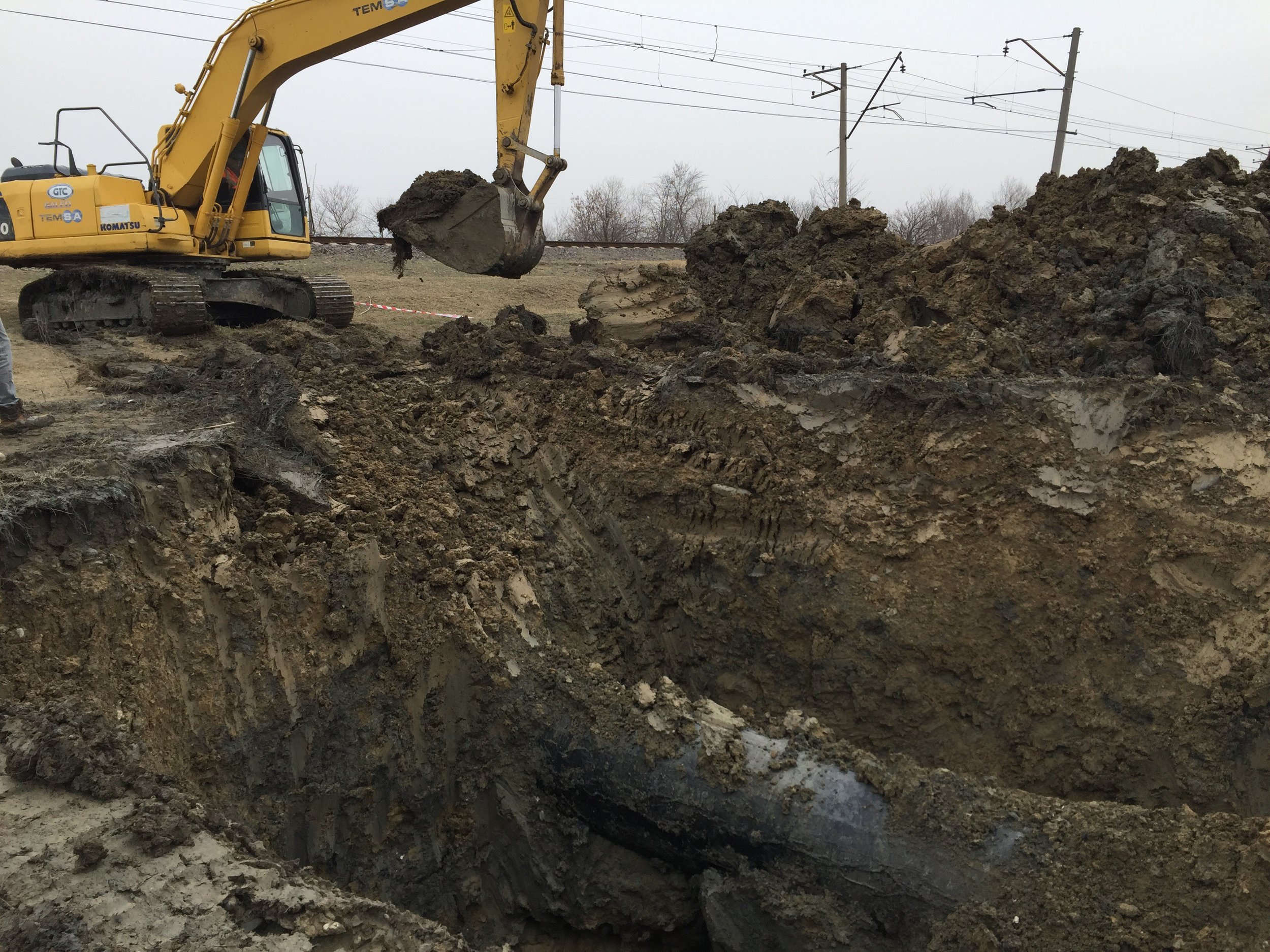
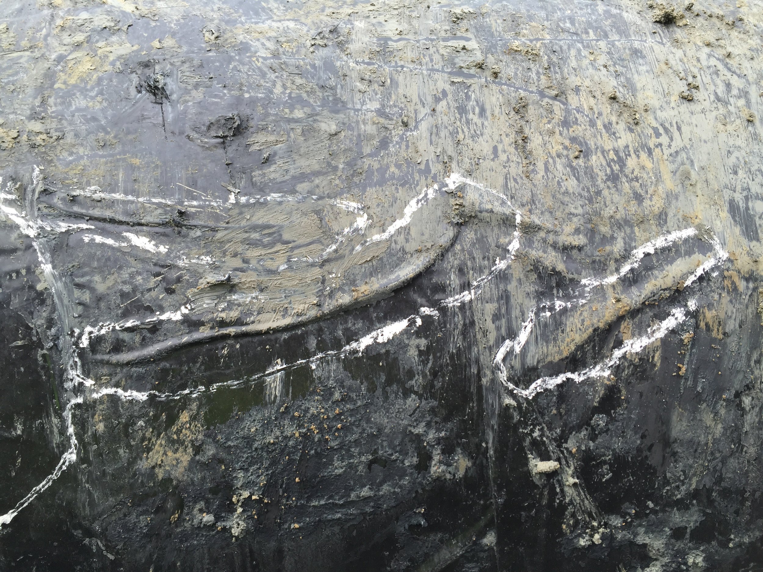
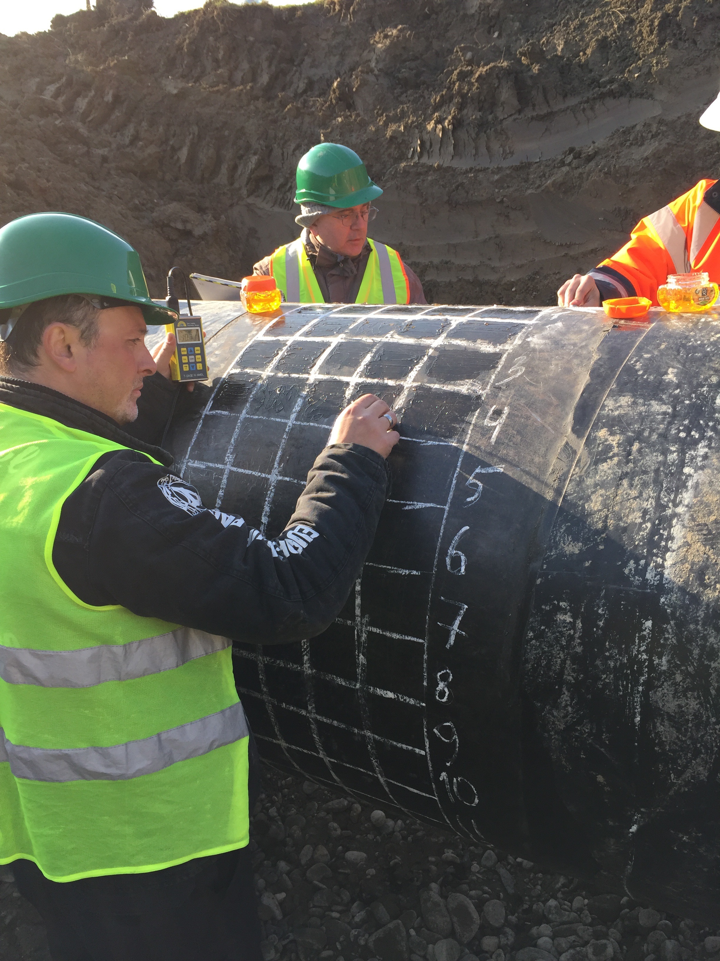
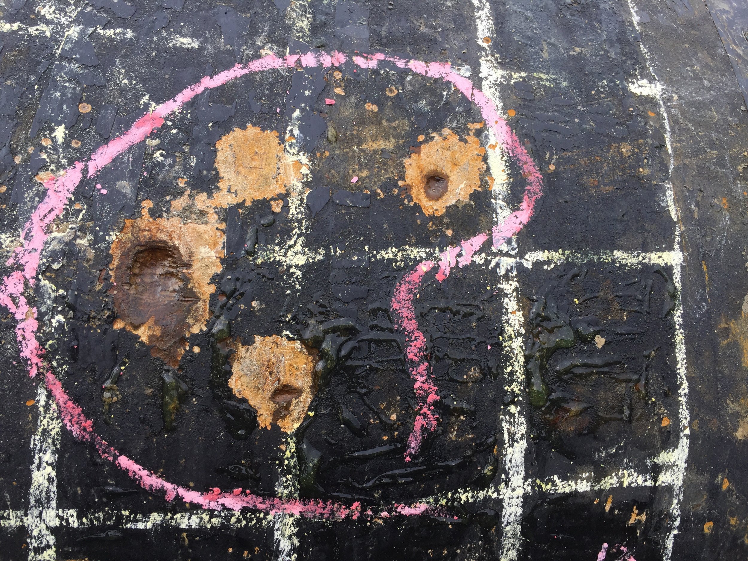
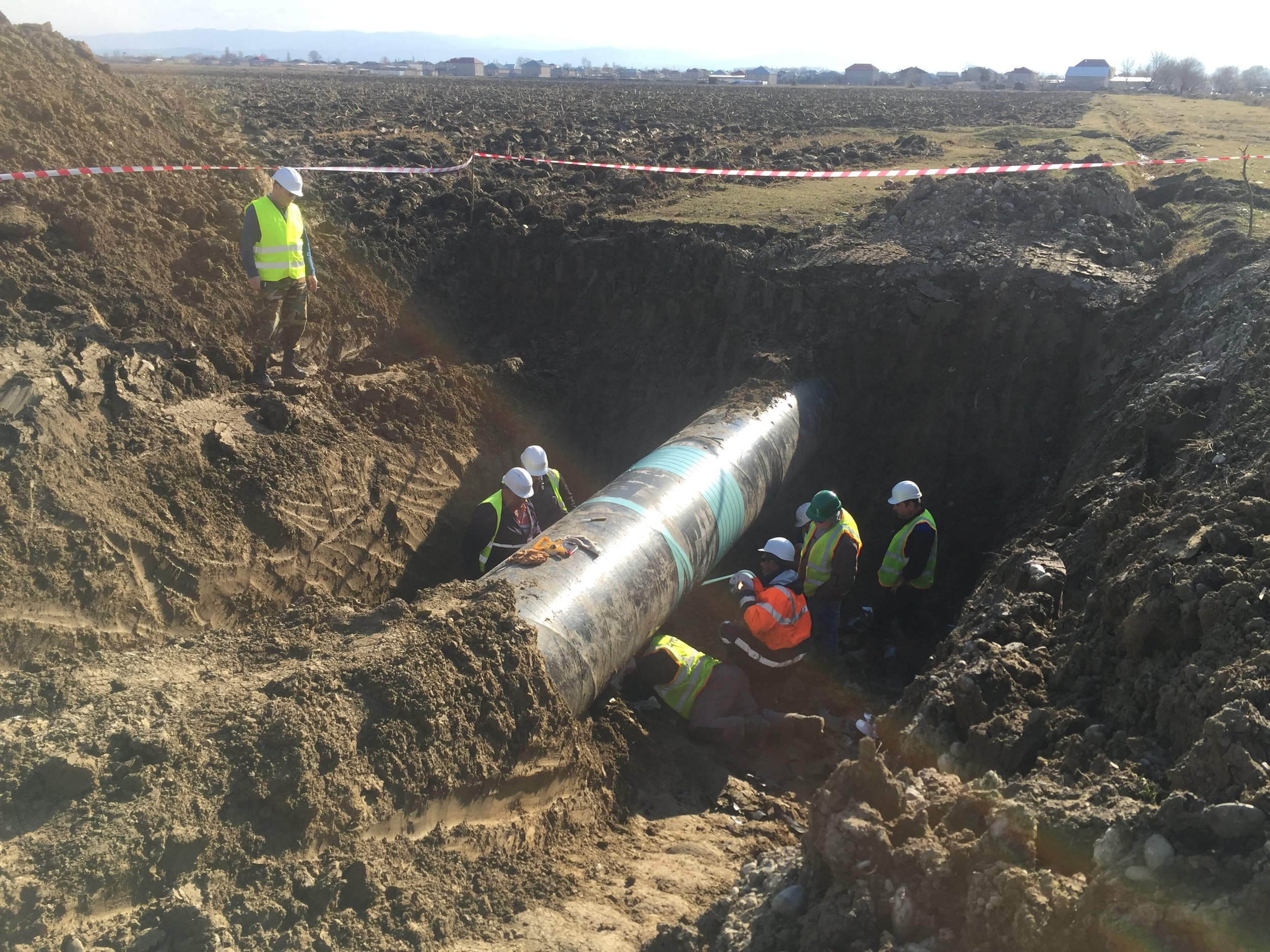
- Direct Assessment [Bellhole Excavation & Testing]
- Post Assessment [Calculation & Reporting]
The flow diagram below shows a general approach to the ECDA Process - evaluation methods may include, but are not limited to those shown here.
Pre-Assessment
Pipe Related
- Material
- Diameter
- Wall Thickness
- Year Manufactured
- Seam Type
- Bare Pipe Sections
Construction Related
- Year Installed
- Route Changes / Modifications
- Construction Practices
- Locations of Valves, Clamps, Insultaing Joints etc
- Locations of and Construction Methods used at Casings
- Locations of Bends including Miter Bends and Wrinkle Bends
- Depth of Cover
- Underwater Sections / River Crossings
- Locations of River Weights and Anchors
- Proximity to other Pipelines, Structures, HV Transmission Lines, Rail Crossings
Soils / Environmental
- Soil Characteristics / Types
- Drainage
- Topography
- Land Use (Current and Past)
- Frozen Ground
Corrosion Control
- CP System Type (Anodes, Rectifiers and Locations)
- Stray Current Sources / Locations
- Test Point Locations (or Pipe Access Points)
- CP Evaluation Criteria
- CP Maintenance History
- Years without CP Applied
- Coating Type – Pipe
- Coating Type – Joints
- Coating Condition
- Current Demand
- CP Survey Data / History
Operational Data
- Pipe Operating Temperature
- Operating Stress Levels and Fluctuations
- Monitoring Programs (Coupons, patrol, Leak Surveys etc)
- Repair History / Records
- Leak / Rupture History
- Evidence of Microbiologically Influenced Corrosion (MIC)
- Type / Frequency of Third Party Damage
- Hydrotest Dates / Pressures
Indirect Assessment
TR & Groundbed Functionality Checks
- TR Output Current
- TR Output Voltage
- Drain Point Potential measurement
- Groundbed Output Capabilities
CIPS (Close Interval Potential Survey)
- Synchronously Interrupted
- On Potential Measurement
- Instant Off Potential Measurement
DCVG (Direct Current Voltage Gradient) Survey
- Synchronously Interrupted
- OL / RE Measurement
- % IR at Defect Calculation
Additional Information Collated
- GPS Coordinates recorded for key features and locations
- Distance measurement of key features and locations
- Photographic records taken for key features
- a.c. potentials measured at all test facilities
- Overview of condition of test facilities and associated connections
- Data logging at identified / possible sources of Stray Current
Direct Assessment
Locations for excavation shall be selected based on the information gleaned from the pre-assessment and indirect assessment procedures.
A minimum of at least one trial pit should be excavated to clarify the effectiveness of the first two procedures.
Post Assessment
All data obtained during the survey activities is provided, generally in both graphical and tabular formats (where appropriate), as well as photographic records, etc.