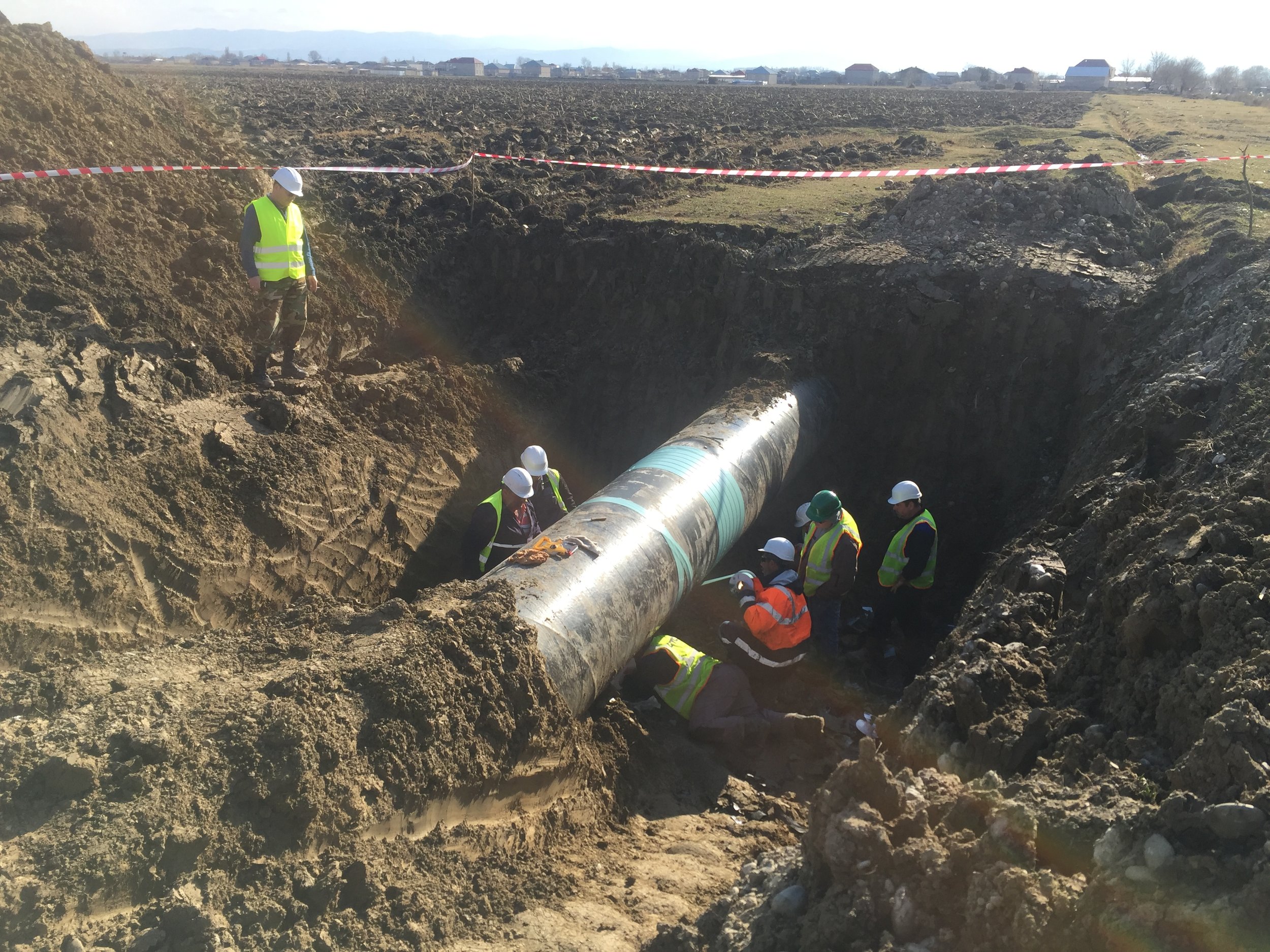
PIPELINE REHABILITATION
When a pipeline is considered for rehabilitation it is inevitably because the pipeline is believed to be in a poor condition, usually due to neglect over the operating life.
On this basis it is usually safe to assume that:
- Whatever coating there was has now deteriorated to the point where it is of no benefit
- Cathodic protection was never properly applied, maintained, or implemented
- Construction records are no longer available
Add to this the unrealistic expectations of lay personnel regarding the cost of pipeline rehabilitation and repairs and there is a huge uncertainty over the prospects for rehabilitation.
Contrary to the opinion of many large pipeline contractors and consultancy groups the best way to rehabilitate a pipeline may not be to dig, expose it all and re-wrap it. Aged pipelines, even those suffering from neglect, are not usually uniformly bad and in need of replacement.
International standards and recommendations are not always helpful in providing guidance. These documents should be treated with caution and recognised for what they are. In the case of standards they are a guide for specialists to employ, not text books. Recommended practices are the opinions of a committee based on their experience and do not have the provenance of a standard.
A good in-line inspection tool can provide the best available information on remaining wall thickness but some tools exaggerate the capabilities of the analysis to provide details on wall thickness, coating disbondment and cathodic protection statements. As in all cases the tool capabilities should be carefully reviewed and verified before committing to major expense.
Above ground inspection is sometimes the only tools that is available to prepare an assessment for rehabilitation and can be used as a stand-alone or as a complimentary set of data for rehabilitation.
It is always good for research and progress to develop new techniques and advanced analysis but we can achieve a great deal if we properly employ the known and existing techniques.
There is no universal solution to pipeline rehabilitation works. Each section of the pipeline has to be considered on its own merits.
The techniques have been successfully applied to many pipelines around the world, even those that the “experts” said could not be rehabilitated.
RECONNAISSANCE & SITE SURVEYS → RISK / PRIORITY MATRIX DEVELOPMENT
Above ground measurements are undertaken including, but not limited to;
- DCVG (Direct Current Voltage Gradient)
- Soil Resistivity
- Visual Inspection at above ground facilities or where pipe is exposed
- Potential measurements
- Potential Gradients
- CIPS (Close Interval Potential Survey)
A Priority Matrix is utilised to assist in selecting suitable locations for excavations and further measurements based on the information gleaned from the Above Ground Measurements phase of the works.
Weightings are applied to various features of the pipeline route to provide an initial assessment. The higher the index then the higher the priority i.e. 0 = low priority, 80 = high priority.
After the initial priority has been established then further key factors are included to provide a final weighting. This final weighting will then be used to supply the final recommendations for excavations.
DIRECT ASSESSMENT, REPAIR & calculation OF MAOP
For each Bellhole assessment the following information is evaluated and recorded;
- Relative Information
- Coating Evaluation
- UT (Ultrasonic Testing) Wall Thickness
- Pit Depths
- Axial Length of "Interactive" Pits
- Soil Resitivity at pipe interface
- Soil pH at pipe interface
- Laboratory Testing of presence of Microbiolgical Activity (e.g SRB etc)
Leaks and coating are repaired as applicable, and tested accordingly.
All data obtained from the Bellhole inspections is then evaluated in accordance with ASME B31G to calculate the Maximum Allowable Operating Pressure (MAOP) for the pipeline.
recommended actions for pipeline rehabilitation
Following all site activities the recommended action to facilitate the rehabilitation of the pipeline to Client requirements can be made. This will consider the following;
Coating Repair
For short sections of poorly coated pipeline, it may be desirable to excavate the length, and recoat it.
Corrosion will only occur where there is a holiday in the coating and therefore repairing the coating at these locations would inhibit the corrosion process from occurring further.
Recoating extensive lengths of pipeline may well be unfeasible due to budgetary constraints.
Mechanical Repairs
Should sections of the pipeline have been deemed to fall below the threshold levels for the operating / testing pressures, than mechanical repairs are possible in order to restore the integrity.
These repairs could entail a direct removal and replacement of a pipe section, or strengthening through reinforcement.
Whilst there are a number of reinforcement products presently on the market, when the length of the section under repair exceeds a certain limit, the repair / replace option can become more economically viable.
Cathodic Protection Systems
There are two types of cathodic protection that can be applied;
- Sacrificial
- Impressed Current
The selection of which type would be best suited to the pipeline is clear from the data collected in the previous phases. This information would not only determine which system to use, but would provide enough information to a design company to ensure a working system is installed.
Sacrificial protection is best used where corrosion / coating damage is localised to small distinct areas, and the resistivity of the soil is below 100 ohm.m.
Impressed current protection is preferred where the general condition of the coating is poor along the entire pipeline length and / or the current demand is higher than expected due to foreign contacts, stray current interference etc.
The two systems are not exclusive from one another, it is common for sacrificial anodes to augment an impressed current system when;
- Design criteria cannot be achieved at both mid-point and drain point
- A source of stray current interference is present


